From Hardcoded Chaos to Dynamic Relationship Rules
How we unified five overlapping relationship mechanisms into a single, config-driven pipeline that understands your Terraform infrastructure.
Gabriel Levasseur
Founder

From Hardcoded Chaos to Dynamic Relationship Rules
If you've ever run terraform graph and piped the output to Graphviz, you know what happens: a wall of nodes connected by a tangled web of edges. Every resource shows up, every implicit dependency gets drawn, and you're left squinting at a diagram that technically represents your infrastructure but tells you nothing useful about it.
Most Terraform visualization tools do the same thing. They dump resources onto a canvas and draw edges. The result is accurate but overwhelming. When you have 200 resources across 7 workspaces, "accurate but overwhelming" means useless.
We built Cora to do something different: create graphs with visual meaning. Resources should nest inside their logical containers. Security groups should display their rules. VPCs should contain subnets, and subnets should contain the resources deployed within them. The goal is a diagram that reveals architecture at a glance rather than hiding it behind complexity.
This post covers how we got there - starting with hardcoded chaos, ending with a dynamic, config-driven relationship pipeline.
The problem: flat graphs tell flat stories
Traditional Terraform graph output treats every resource as a peer. An aws_instance sits at the same level as an aws_vpc. An aws_security_group_rule floats alongside the security group it belongs to. Dependencies exist, but they're drawn as lines between equals.
This approach ignores the mental model engineers actually use. When you think about your infrastructure, you don't think "these 47 resources all depend on each other." You think "I have a VPC with public and private subnets. My ECS services run in the private subnets behind a load balancer. The RDS instance sits in its own subnet group."
The hierarchy matters. The containment matters. Showing it requires understanding relationships beyond Terraform's dependency graph.
See the difference
Without relationship awareness, resources appear as a flat grid - every resource at the same level, every connection a generic dependency line.
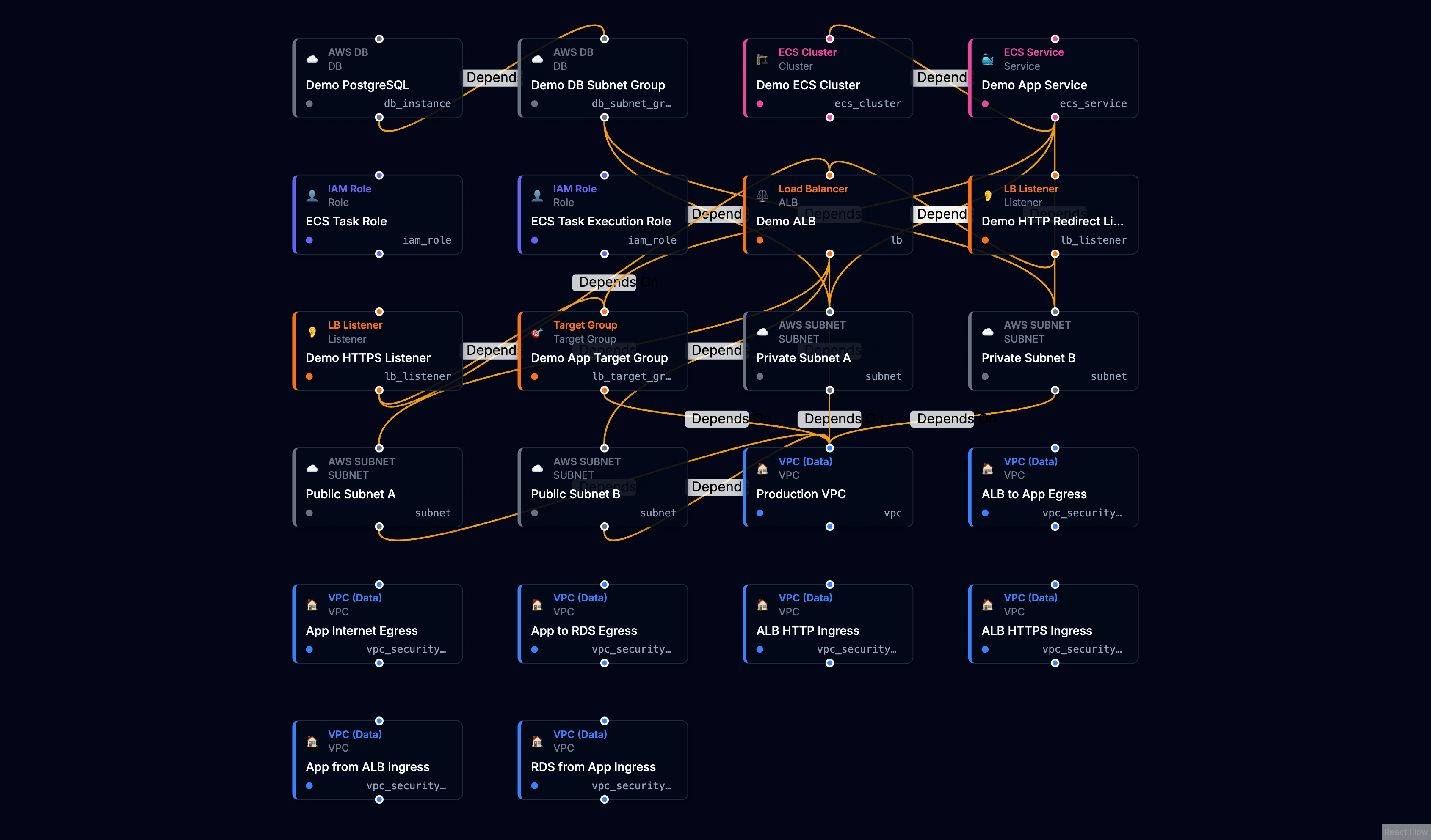
With dynamic relationship rules, the same infrastructure reveals its architecture. VPCs contain subnets. Security groups nest their rules. Load balancers connect to their listeners and target groups.
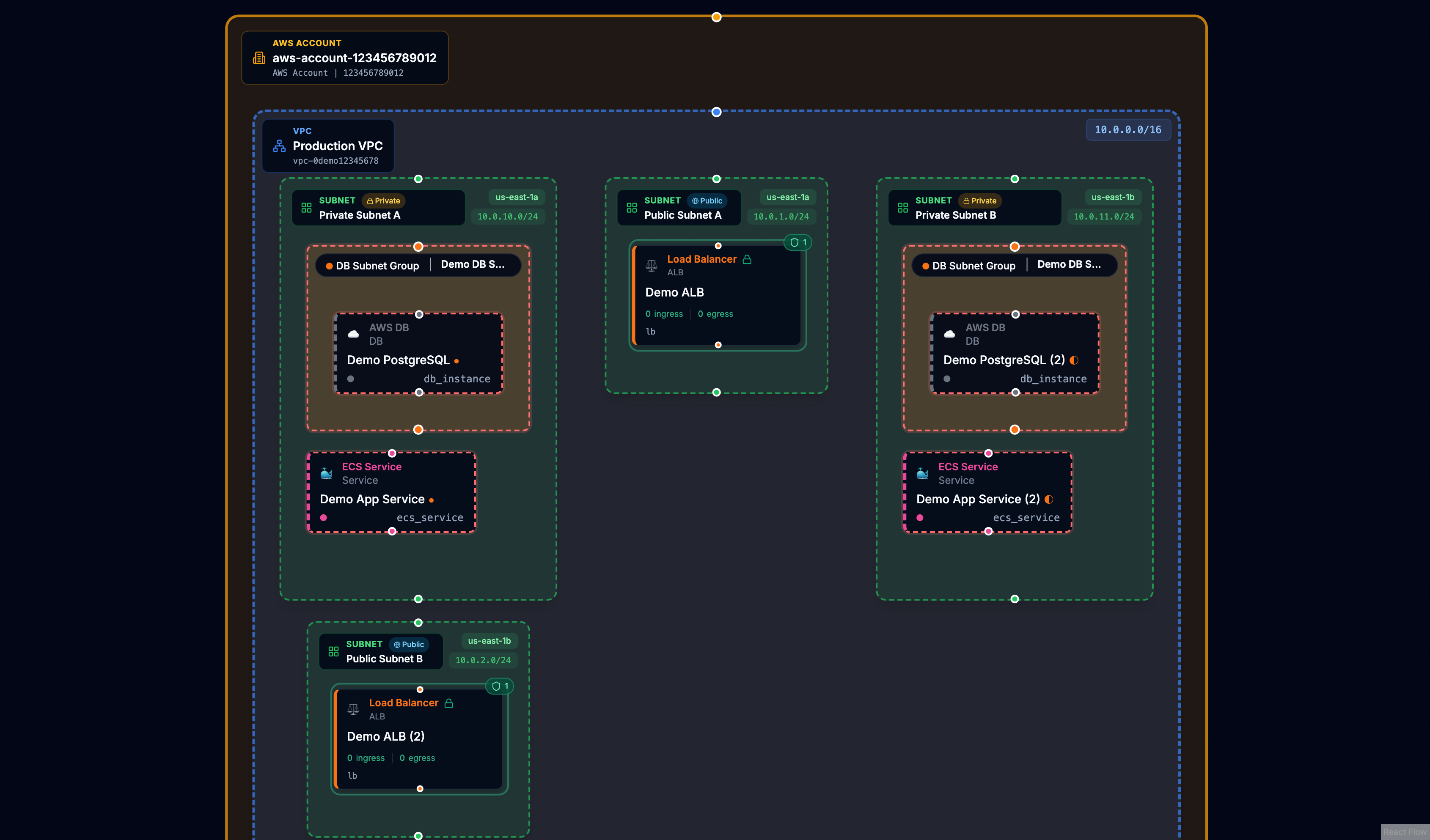
The underlying data is identical. The difference is understanding what the relationships mean.
Our first approach: hardcode everything
When we started Cora, the natural solution was to encode what we knew. Subnets have a vpc_id attribute that points to their VPC. Security group rules reference their parent security group. ECS services reference task definitions.
So we wrote code. A lot of code.
We built a function that would scan resource attributes and create relationships based on resource type. A switch statement mapped each type to its known patterns:
switch (resource.type) {
  case 'aws_subnet':
    // Extract vpc_id from attributes, create BELONGS_TO edge
    break;
  case 'aws_ecs_service':
    // Extract cluster ARN, task definition ARN, subnet IDs...
    break;
  case 'aws_lb_listener':
    // Extract load_balancer_arn, create LISTENS_ON edge
    break;
  // ... 12+ more cases
}
This worked. Subnets nested inside VPCs. Security groups displayed their rules. The graphs started to tell stories.
But every new resource type meant a code change and a deployment.
The problem grows: five overlapping mechanisms
Over time, our relationship detection grew organically in multiple directions:
-
Terraform Dependencies - We honored
instance.dependenciesfrom the state file, creatingDEPENDS_ONedges directly. -
Attribute Scanning - A regex-based scanner would look for ID and ARN patterns in any attribute, creating edges when it found matches.
-
Hardcoded Switch Statements - The hand-written logic for specific resource types like subnets, ECS services, and load balancers.
-
Early Config Rules - Some rules stored in the database, processed by a separate code path.
-
Database Resolution - A resolver that queried for targets, duplicating logic from other paths.
Plus post-hoc inference that would patch missing containment after everything else ran.
The import logic became sprawling and fragile. When something broke, debugging meant tracing through five different code paths to understand which mechanism created (or failed to create) a relationship.
Every time we wanted to support a new resource type or fix an edge case, we had to modify code, test across all the overlapping systems, and deploy. The fragmentation meant that patching one path often caused regressions in another.
The solution: a unified relationship pipeline
We stepped back and designed a clean architecture with one goal: rules as data, not code. Every semantic relationship - whether it's a subnet belonging to a VPC or a listener forwarding to a target group - gets defined in a configuration rule, not a switch statement.

The pipeline processes each resource through four stages:
Stage 1: Intent Collection - The system loads all enabled rules and matches them against each resource by type. When a rule matches (say, an aws_lb_listener against the "Listener forwards to Target Group" rule), it extracts the relevant attribute values and creates a relationship intent.
Stage 2: Target Resolution - Each intent needs to find its target. The system queries the workspace for resources matching the target type, then applies the rule's match strategy - comparing IDs, ARNs, names, or DNS names to resolve a concrete target resource.
Stage 3: Edge Writing - Resolved relationships get batched and written to the graph database. This stage also applies nested display settings, marking which resources should visually nest inside their parents.
Stage 4: Terraform Dependencies - Finally, direct dependencies from the Terraform state file create their own DEPENDS_ON edges. These preserve Terraform's explicit dependency intent alongside our semantic relationships.
What a rule looks like
Each rule is a declarative configuration that tells the pipeline how to find and create a relationship:
{
  id: 'builtin-subnet-vpc',
  name: 'Subnet belongs to VPC',
  sourceTypes: ['aws_subnet'],
  targetTypes: ['aws_vpc'],
  sourceAttributePaths: ['vpc_id'],
  targetAttributePaths: ['id'],
  matchStrategy: 'id',
  relationshipType: 'BELONGS_TO',
  containerSemantics: 'target-contains-source',
  nestedDisplay: 'source-in-target',
  enabled: true,
}
The key fields:
- sourceTypes / targetTypes - Which resource types this rule connects
- sourceAttributePaths - Where to find the reference in the source resource
- matchStrategy - How to match values (
id,arn,name, ordns_name) - nestedDisplay - Whether to visually nest resources (
source-in-targetortarget-in-source)
When Cora imports state, it loads all enabled rules, evaluates each resource against matching rules, resolves targets, and writes edges. No switch statements. No special cases scattered across the codebase.
Multi-level nesting: load balancers in action
The real power of config-driven rules shows up when you need multi-level nesting. Consider a typical ALB setup: a load balancer has listeners, and each listener forwards traffic to target groups. In a flat visualization, these appear as six separate resources with lines between them. In Cora, you see the hierarchy.
This requires two rules working together.
Rule 1: Listener nests inside Load Balancer
{
  id: 'builtin-listener-lb',
  name: 'Listener on Load Balancer',
  sourceTypes: ['aws_lb_listener', 'aws_alb_listener'],
  targetTypes: ['aws_lb', 'aws_alb'],
  sourceAttributePaths: ['load_balancer_arn'],
  matchStrategy: 'arn',
  relationshipType: 'LISTENS_ON',
  nestedDisplay: 'source-in-target',
}
The listener has a load_balancer_arn attribute. The rule extracts it, matches it against load balancer ARNs in the workspace, and creates a LISTENS_ON edge. The nestedDisplay: 'source-in-target' setting tells the UI to render the listener inside the load balancer node.
Rule 2: Target Group nests inside Listener
{
  id: 'builtin-listener-tg',
  name: 'Listener forwards to Target Group',
  sourceTypes: ['aws_lb_listener', 'aws_alb_listener'],
  targetTypes: ['aws_lb_target_group', 'aws_alb_target_group'],
  sourceAttributePaths: ['default_action[*].target_group_arn'],
  matchStrategy: 'arn',
  relationshipType: 'FORWARDS_TO',
  nestedDisplay: 'target-in-source',
}
Notice the attribute path: default_action[*].target_group_arn. The [*] wildcard tells the rule engine to iterate over every element in the default_action array and extract the target_group_arn from each one. A listener might have multiple actions - a default forward, a redirect, a fixed response - and some of those actions reference target groups. The wildcard ensures we catch them all, creating relationships for every target group the listener routes to.
The nestedDisplay: 'target-in-source' setting here is the inverse of the first rule. It tells the UI to render the target group inside the listener, creating the full hierarchy: ALB → Listener → Target Group.
Adding support for a new nesting pattern - say, API Gateway stages inside APIs - is now just data. Create a rule, set the attribute paths, enable it. No code changes, no deployments, no risk of breaking existing patterns.
What we shipped
The system now includes about 45 built-in rules covering:
- VPC/Networking - Subnets, security groups, internet gateways, route tables, NAT gateways
- Compute - ECS services and task definitions, Lambda functions, EC2 instances
- Load Balancing - ALBs, listeners, target groups
- Databases - RDS instances, DB subnet groups, Elasticache clusters
- IAM - Roles, policies, instance profiles
- DNS - Route53 records pointing to load balancers
These built-in rules handle the vast majority of AWS infrastructure patterns out of the box.
The result: clearer graphs, faster iteration
The unified pipeline simplified the import flow dramatically. More importantly, it changed how we work:
- New resource types require adding a rule, not modifying code
- Debugging means checking if a rule exists and is enabled
- Iteration is fast - we can ship new relationship patterns without touching the core pipeline
The graphs Cora produces now show architecture. VPCs contain subnets. Subnets contain the resources deployed within them. Security groups display their rules. Load balancers show their listeners. The visual hierarchy matches the mental model.
What's next: custom rules for your patterns
The same architecture that lets us iterate quickly internally could let you define your own rules. If your team has custom naming conventions, internal resource types, or infrastructure patterns specific to your organization, you shouldn't have to wait for us to add support.
We're exploring a rule editor that would let you create, test, and enable custom relationship rules directly in Cora - no code, no deployments. Define the source and target types, specify the attribute paths, and see the results immediately in your graph.
If custom rules would be valuable for your team, we'd love to hear about your use cases. Reach out and help shape what this feature becomes.
If you're managing Terraform infrastructure and want to see your architecture clearly, import your state into Cora and see the difference structure makes.
Try Cora with your Terraform state
See your infrastructure as an interactive diagram. Easy setup, no complexity.
Get Started Today!Keep reading
View all
Terraform: Unlock Flexibility with the Open-Closed Principle
Discover how to build modules that grow with your team. Learn to design for extension and create a 'batteries-included' experience without the bloat.
Gabriel Levasseur
Founder

One Resource Changed. One Incident.
Your Terraform plan only shows what's changing in one workspace. Cora's PR Risk Assessment reveals the blast radius across all your infrastructure, so you see the real impact before you merge.
Gabriel Levasseur
Founder
Stop Building Terraform God Modules
Why modules with 40 inputs and passthrough variables slow teams down—and how to design reusable building blocks instead.
Gabriel Levasseur
Founder